

13 articles about "Magnetic Recording" - RCA (1964)
Thirteen technical papers by RCA scientists and engineers.
.
TV TAPE RECORDING - A REVIEW OF TECHNIQUES AND EQUIPMENT (1964)
A. H. LIND, Mgr. - Studio and Scientific Instruments Engineering Broadcast and Communications Products Division, Camden, N. J.
.
A. H. LIND
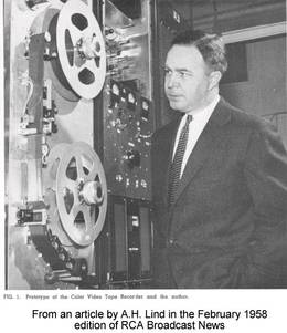
- Mr. Lind in 1958

- A. H. LIND, Mgr. - Studio and Scientific Instruments

A. H. LIND received the BSEE in 1946 and the MSEE in 1949, both from the University of Wisconsin. He has been a member of the engineering staff of the RCA Broadcast and Communications Products Division since 1946; until 1950, he was engaged in TV camera development and design.
From 1950 to 1953 he was Manager, TV Terminal Equipment Engineering and directed the development and design of such terminal equipment as sync generators, video switches, video distribution amplifiers, etc.
From 1953 to 1959 he was Manager, Broadcast Audio and Mechanical Devices Engineering; this group developed and designed audio and TV magnetic recorders, TV projectors, associated film equipment, and broadcast audio equipment. From 1959 to 1962 Mr. Lind was Manager, Electronic Recording Products Engineering and directed the development and design of magnetic tape recording equipment.
In February 1962, he was also made responsible for Scientific Instruments Engineering, which has the electron microscope as its principal product. Mr. Lind is presently Manager of Studio and Scientific Instruments Engineering. He is a member of the IEEE, the SMPTE, and the Franklin Institute; also, Tau Beta Pi, Eta Kappa Nu, and Pi Mu Epsilon.
He has participated as a member of many industry technical committees and currently is chairman of the SMPTE Video Tape Recording Committee.
TV TAPE RECORDING - A REVIEW OF TECHNIQUES AND EQUIPMENT - About the RCA color television tape recorder
Since the announcement in 1959 of an RCA color television tape recorder, a succession of models have appeared. These are reviewed briefly in tracing the development of the television tape recorders down to the current all-transistor types TR-22 and TR-3, -4, and -5, and the major technical efforts that have led to improved performance.
Unser Kommentar zu diesem Artikel (written by gr in 2014)
You need to know, this is a RCA "promotion"- paper. The truth is, the early 1956 RCA video- recorder- development failed in quality and stability - and AMPEX found the way to get his system running and AMPEX got the patents. - But AMPEX was forced by US-government order to exchange (some) patents with RCA to have a second source of suppliers for this important quadruplex technology. - The second truth is, that RCA enhanced the fully tube- (Röhren-) driven AMPEX quadruplex VR-1000 recorder with a fully transitorized version in 1959. - AMPEX as the inventor was disgraced (blamiert) and took the RCA lug and the "patent- exchange"- agreement, to improve his own recorder. The story is much longer and very interesting. We have this AMPEX story in German language here.
SOME BACKGROUND (von Mr. Lind, dem Autor dieses Artikels )
One of the most intriguing (faszinierende) applications of magnetic recording since the early work of Poulsen is the use of this technique to record television picture signals. The recording and storing of electrical signals by magnetizing microscopic oxide particles through the application of a magnetic field has been generally known for decades.
The most successful magnetization method has been to immerse the oxide particles in a fringe field emanating from a gap in soft magnetic material; the soft magnetic core is part of an electromagnet. Such an assembly is universally called a magnetic head.
To obtain maximum efficiency, the iron oxide particles customarily coated on plastic tapes and the gap of the magnetic head are held in as intimate proximity as possible. The magnetic head gap-size determines, in practice, the shortest wavelength that can be recorded. A spacing loss due to surface roughness also influences the intimacy of contact and can be a factor in determining the shortest useful wavelength that can be recorded.
The shortest wavelength that can be recorded and the electrical signal frequency corresponding to this wavelength are directly related by the relative motion of the tape and the magnetic head. Thus, the matter of head-to-tape speed relationship becomes paramount when high-frequency recording is considered.
For example, if the minimum wavelength usefully recorded is assumed to be 200 microinches (0.000200 inch) - then a head-to-tape speed of 1,000 ips (inches per second) is required to record a signal of 5 Mc (= MHz - assuming the signal is recorded in a single channel). Experience has shown that satisfactory tape recordings can be made with tracks, or patterns, only a few thousandths of an inch wide.
(For more-detailed discussions of RCA television tape recording techniques and equipment, see the papers listed in the Bibliography. - ganz unten auf dieser Seite)
.
Introduction
- Fig. 1 - Quadruplex TV tape recording.

Perusal of the technical literature reveals that a great deal of research on various approaches to wideband signal recording preceded the actual design of a workable, practical wideband video tape recorder.
In addition to the tape motion required to transport the magnetic medium past the magnetic heads, a much higher head-to-tape speed is achieved by moving the head so that it scans transversely in a narrow path across the tape oxide surface.
To provide a succession of such transverse tracks without loss of signal, four magnetic heads were chosen to scan the tape in sequence. The heads are mounted in 2-inch-diameter wheel which is rotated at high speed to achieve the necessary head-to-tape speed. This time-sequential multiplexing of the four heads gave rise to the choice of the descriptive term quadruplex to designate the system.
EFFECT OF COLOR TV
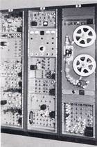
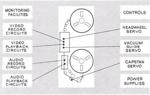
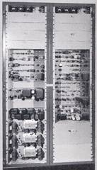
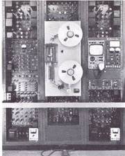
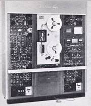
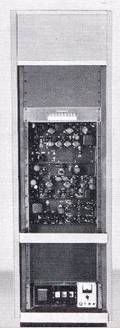
- Fig. 2 - The VTRX color tape recorder was housed in seven racks (one, a monitor, is not visible here); left photo shows (I to r) the signal, control and transport racks;

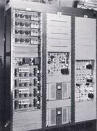
- right photo shows (I to r) power supply and two servo racks.

The potential of color tv made it mandatory that a production-line TV recorder (also volle Studioqualität) be capable of recording and reproducing both black and white and color video signals.
Through the combined and coordinated efforts of many engineers and scientists at the RCA Laboratories, RCA Defense Electronic Products, and the group then called RCA Industrial Electronic Products, an acceptable system was developed and designed.
(Sorry, thats partially wrong :The quadruplex system b&w and color ist taken from AMPEX but the solid state color version is developed by RCA)
Public announcement of the color tv recorder was made by demonstrations to the technical press in October 1957 (by the competitor AMPEX).
In Europa haben wir vom Farbfernsehen vielleicht mal schlecht geträumt, selbst bei der Robert Bosch Fernseh GmbH in Darmstadt nicht.
In 1958, a small number of engineering prototypes, designated VTRX (Fig. 1), were delivered for use - principally by NBC for color program delay between the east and west coast. It contained all the basic functions required for a TV tape recorder (Fig. 2).
While the video recorder development gave rise to increased sophistication in the video signal-handling circuitry, the areas in which major efforts were applied were the servomechanism, electromechanical, and precision mechanical assemblies.
Mechanical tolerances of microinches (millionths of an inch) and seconds of arc become commonplace in quantity production of assemblies at competitive prices.
.
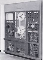
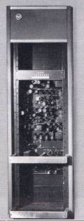
- Fig. 3 - TRT-1 A first production-model TV tape recorder: five racks were used; left photo shows signal,

- transport and control racks; right photo shows power supply and servo racks.

RCA TRT-1 RECORDERS
Accelerated development and design effort resulted in the first production model, the TRT-1A (Fig. 3). Deliveries from production began in 1959.
Although numerous improvements were made in performance over the VTRX, perhaps the most substantial gains were in servomechanism stability and video headwheel panel improvements.
Some of the video headwheel panel improvements can be appreciated by observing the contrast between the VTRX panel and the TRT-1A panel shown in Fig. 4.
.
RCA TRT-1B RECORDER
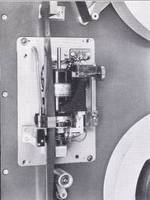
- Fig. 4 - Left photo: VTRX headwheel-panel assembly; right photo, TRT-IA headwheel

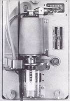
- panel assembly. In both, the entire headwheel panel assembly is demountable.

As the TRT-1 A recorders were placed into operation, much valuable field experience started feeding back to the design engineers.
This, plus benefits from continuing development work, were incorporated in a redesigned recorder, the TRT-1B, which became available in 1960.
The TRT-1B had increased operational flexibility, better monitoring facilities, and included a signal processing amplifier that provided clean sync and blanking in the output signal and was the first transistorized unit used in tv recorders.
.
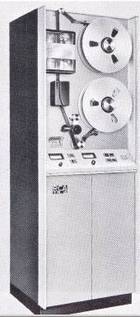
- Fig. 5 - TR-11 TV tape recorder; this unit shows a 40% decrease in size, employing only three racks.

TR-11 RECORDER
As experience with the TRT-1's grew, it became clear that a simpler machine could make good pictures. By limiting the operational flexibility and monitoring facilities, a second, lower-cost recorder was made available in 1961.
Because of the heavy engineering load in Camden laboratories, this recorder, the TR-11, was engineered in the Broadcast and Communications Products Division, Hollywood, California plant.
A substantial reduction in size was achieved (compare Fig. 5 and Fig. 3), with corresponding reduction in power requirements. The TR-11 was intended primarily for small broadcast stations and educational tv applications.
.
TR-22 TRANSISTORIZED RECORDER


The increasing importance of transistors and the desire for more compact recorders were key considerations behind the TR-22 all-transistor recorder (Fig. 6), that was introduced at the 1961 NAB (National Association of Broadcasters convention). The TR-22, shown in Fig. 6, has been a very gratifying commercial success. The basic recorder is completely a solid-state design. The only vacuum tubes are in the picture and waveform monitors. The size, weight and input power are all very substantially reduced from that of the TRT-1B predecessor.
Two versions of the TR22
The TR-22 was designed in two versions: The first is a domestic version for 525-line, 60-field tv signals with 60-cycle ac power. The second is a 3-standard switchable recorder designed to accommodate 525-line, 60-field; 625-line, 50-field; and either 405-line, 50-field or 819-line, 50-field signals. In the second case, the input power is 230-volt, 50-cycle AC.
LATEST FAMILY OF TV TAPE MACHINES: TR-3, TR-4, AND TR-5
- Fig. 7 - TR-3 all-transistor TV tape player represents the first unit to be devoted to "playback only."

The newest series of RCA television tape machines includes the TR-3, TR-4, and TR-5. These new machines reflect design advances in decreased size, improved performance, lower power consumption, and greater mobility. The machines continue to employ the quadruplex recording system and thus are fully compatible with the more than 2,000 (mostly AMPEX) professional tv tape recorders now in worldwide use.
The TR-3 is a playback-only machine (Fig. 7). It is analogous to a tv film chain, since prerecorded tapes are replayed in it with its output being a video signal. It is very appropriate to introduce a playback-only machine at this time because it has become common practice for broadcast studios to utilize one or more tape recorders to play back tapes previously recorded on other machines.
The TR-4 is an expanded version of the TR-3, in which recording and monitoring circuitry is added. It thus becomes a smaller edition of the well-accepted TR-22.
The TR-5 is packaged in a small cabinet which can be easily moved and transported, and complements the TR-3 in that it is intended as a recorder. Its mobility for both in-studio and remote recording makes it very attractive as an addition to existing tv tape recorder installations. All three of the new tape recorders are available in both domestic and international models. The international models can be switched for operation at either of two scanning standards.
THE "PIXLOCK" SERVO
- Fig. 8 - TRT-1 pixlock servo control unit stabilizes the mechanical scanning within ±100 nsec.

During the period of TR-22 development and design, an accessory precision headwheel servo unit for the TRT-1 recorders was designed. This unit, called the pixlock servo (Fig. 8), has subsequently been incorporated in a large portion of the TRT-1 recorders. In addition to providing substantially improved performance (absolute time lock of the playback signal to within ±0.1 usec with respect to a crystal controlled reference timing signal), this accessory was the second all-transistor unit to become a commercially designed product. It reduced the space and power requirements for the headwheel and capstan servos by factors of 8 and 10, respectively.
.
- Fig. 9 - TR-2 economy TV tape recorder is a modification of TR-11.

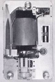
- Fig. 10 - Air bearing head-wheel panel assembly.

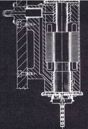
- Fig. 11 - Air bearing panel.

As a result of this substantial space saving, the TR-11 was redesigned to incorporate the improved performance provided by the transistor servo circuits as well as the more compact units. This redesign also presented the opportunity to make numerous other design improvements including the ability to handle color signals. The redesign recorder became the TR-2 (Fig. 9).
SLOW-SPEED ASSEMBLY
An important step forward was made when it became possible to reduce the longitudinal tape speed from 15 ips to 7.5 ips. This development was made available as a modification accessory for all existing RCA recorders in 1962; this modification added the 7.5-ips speed as a switchable second speed.
The 50% saving in initial tape cost was an important economic consideration. The reduction in size and weight of a given recording was also important for both storage and shipping reasons.
The 7.5-ips tape speed was made feasible by greatly improved wear, life, and sensitivity performance of the video magnetic head assemblies. A continuing development program had raised the head life from a dubious 100 hours (the guaranteed minimum) to an expectancy in excess of 400 hours. Other head-design changes permitted the recording of the necessary half-width video tracks with hardly any discernible reduction in signal-to-noise performance.
VIDEO MAGNETIC HEADWHEEL ASSEMBLY
In addition to the basic task of providing workable video magnetic heads mounted in a rotating wheel, many problems were encountered and overcome in providing a long-lasting, highspeed, high-performance mechanism in which the heads are mounted.
Two areas of substantial development and design effort are the bearings used for the high-speed shaft and the slip-ring brush assembly which is required to carry the electrical circuits to and from the magnetic heads.
Through the years, effort has been applied to obtain "ball bearings" that are well manufactured, carefully and properly lubricated, and designed to work economically and well in the overall assembly; thus, a very satisfactory level of performance has been achieved. Constant vigilance in the area of quality control is vital to maintaining satisfactory performance.
New air lubrication
An alternative of using air films for lubrication of the rotating high-speed shaft was suggested several years ago after the successful application of this technique to precision tape capstan assemblies by DEP Applied Research.
In 1960, the first application of air bearings in headwheel panel assemblies was made experimentally (Anmerkung : bei den großen RCA qudruplex VTRs, AMPEX hatte das schon deutlich früher.)
The resulting product design is shown in Fig. 10. Both the radial and axial bearings are air-lubricated. Air is introduced into the bearing journals from an external source of supply at approximately 35 psi. Since the rotating shaft does not make contact with the bearing journals, (Fig. 11) the only points of mechanical load are the frictional load of the slip-ring brushes and the frictional drag of the magnetic heads on the tape oxide surface.
As a result, the servo performance with respect to time stability (freedom from jitter) is substantially improved both in peak performance and average performance. Furthermore, bearing life is substantially extended and is limited primarily by the ability to keep the air supply to the bearings clean.
New - the rotating transformer
A continuing program on materials for improved magnetic head pole pieces and coil cores resulted in the introduction of alfecon in 1961. This pole-tip material increased the service life by three to four times over that achieved with the previously used alfenol. Work continues in this area with the expectancy that ferrite materials in some still-to-be-determined form will be a further step toward longer head life with improved signal performance.
COLOR TV RECORDING REFINEMENTS
Early work with the quadruplex recorder established that its time stability for periods of one or two tv lines was adequate to maintain the accuracy of the chrominance portion of the color signal to the corresponding subcarrier burst signal adequate for color playback.
However, since color receivers did not, and still do not, demodulate the color information on a line-at-a-time basis, this stability is not adequate.
Double-Heterodyne Technique
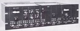
- Fig. 12 - Color signal processing rack for TRT-1A.

- Fig. 13 - Color signal processing rack for TRT-1B.

The first successful approach to compensating for the phase errors introduced by the recorder was to use a double-heterodyne technique that in effect stabilized the color phase errors which are inherent in the basic recorder.
This technique utilizes a local oscillator which is locked to the tape color subcarrier bursts on a line-at-a-time basis; the chrominance signal is then double heterodyned; first, against an oscillator which varies as the tape burst signal varies, and secondly, against a stable carrier locked to the local crystal-controlled color subcarrier standard.
Fig. 12 shows the heterodyne color processing equipment used with the TRT-1A recorder.
.
The heterodyne color processing equipment was redesigned to improve its stability, reduce the distortion in waveform processing and reduce its size for the TRT-1B. This equipment is shown in Fig. 13.
The double-heterodyne approach to color processing involved a degree of compromise in the overall frequency response performance and the overall time-stability performance of the TRT-1 recorders. Since it was not practical to handle the entire video spectrum in the heterodyne process, frequency division of the video signal was introduced. Only the high-frequency chrominance portion of the signal was passed through the heterodyne process, thus any jitter that appeared in the low-frequency "luminance" signal appears at the output of the machine unattenuated.
Automatic Timing Control
Other approaches that might permit handling the entire video signal through one path and controlling the delay or velocity of transmission through that path were investigated.
Practical success was reached when electrically controllable delay networks were developed, based on the use of electrically variable capacitors that are simply specially-designed, reverse-biased semiconductor diodes. This technique of the stabilization was used first in monochrome automatic timing control for the TRT-1 series of recorders.
After the successful introduction of monochrome units (in which the timing error is established by comparing the trailing edge of the tape signal sync with an external stable sync signal and subsequently using this error signal to modulate the delay in an electrically controllable delay network) a next step was to apply the same technique to process the tape-playback color signal.
.
.
- Fig. 14 - The six color ATC modules for TR-22, shown partially withdrawn.

In the case of a color signal, the tape color subcarrier burst phase is compared to a stable external color sub-carrier signal to determine the error. The error signal is then used to modulate the delay in a modest range delay network to eliminate the chrominance phase errors incurred in the tape recording-playback process.
The color automatic-timing control units (Fig. 14), when incorporated in the TR-22 TV tape recorder, make the color recorder performance substantially better than that achieved with the double-heterodyne equipment.
CONCLUSION (in the year 1964)
The tv tape recorder has justified its widespread acceptance in the tv industry on both technical and commercial grounds. As it continues to mature, those closely associated with it anticipate many more interesting and rewarding developments.
BIBLIOGRAPHY
.
- 1. Lind, A. H., "Engineering Color Video Tape Recording," RCA
- 2. Lind, A. H., "The TR-22 - RCA's Transistorized TV Tape Recorder," RCA
- 3. Luther, A. C. and Hurst, R. N., "The TR-22 - A Deluxe, All Transistor Television Tape Recorder," Broadcast News, Vol. 115, Nov. 1962.
- 4. Melchionni, B. F., "Magnetic Head Development and Design," RCA
- 5. Isom, W. R., "Advanced Recording Techniques," RCA
- 6. Bick, J. B. and Johnson, F. M., "Magnetic Heads for TV Tape Recording," RCA
- 7. Johnson, F. M., "Air Bearing Headwheel Panels for RCA TV Tape Recorders," Broadcast News, Vol. 113, May 1962.
- 8. Lind, A. H., "Color Processing in RCA Video Tape Recorder," Broadcast News, Vol. 99, Feb. 1958.
- 9. Luther, A. C, "Modern Color Television Tape Recorders Using Automatic Timing Correction," RCA
.